KS0306 Micro:bit V2.0 beginning Starter Kit
Introduction:
Micro:bit, designed by BBC, helps senior students learn programming. It is rich in on-board source including a 5*5 LED dot matrix, two programmable buttons, a compass, micro USB ports and a Bluetooth module.
It is only half the size of a credit card (4cm×5cm), but very mighty. Moreover, it can be used to edit video games, sound and light interaction, robot control, scientific experiments, wearable device and so on.
The new micro:bit V2 has a MEMS microphone, a touch logo and a buzzer which you can play sound everywhere. In addition, the edge connector can fix the crocodile clip easily.
Its sleep mode can be activated by pressing long reset/power button, which can reduce the power consumption of battery. And its CPU performance is better than V1.5. To sum up, its performance increase a lot.
The tutorials and test code are provided. What do you create today?
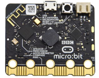
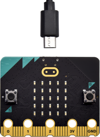
Front and back side
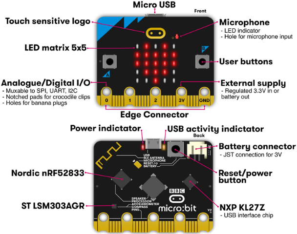
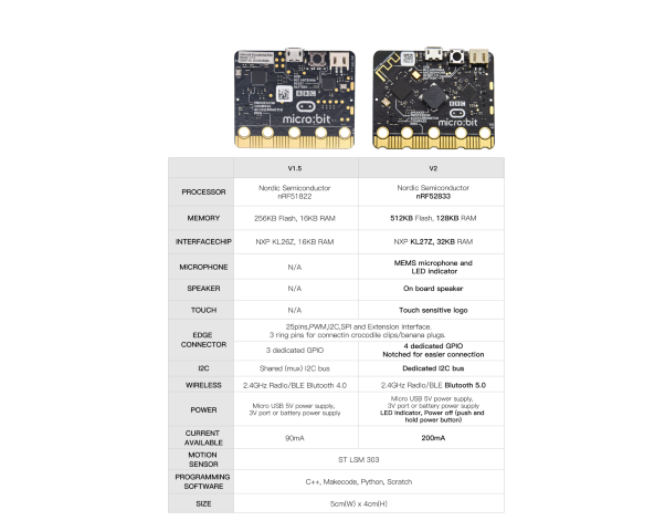
Micro:bit V2
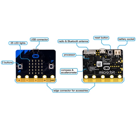
Micro:bit V1.5
You can reboot micro:bit V2 when pressing reset and power button.
LED will get dark and the power-saving mode will be activated if you keep pressing reset and power button, which can make the life expectancy of batteries longer and activate micro:bit.
More resource:https://tech.microbit.org/hardware/
https://microbit.org/new-microbit/
https://www.microbit.org/get-started/user-guide/overview/
https://microbit.org/get-started/user-guide/features-in-depth/
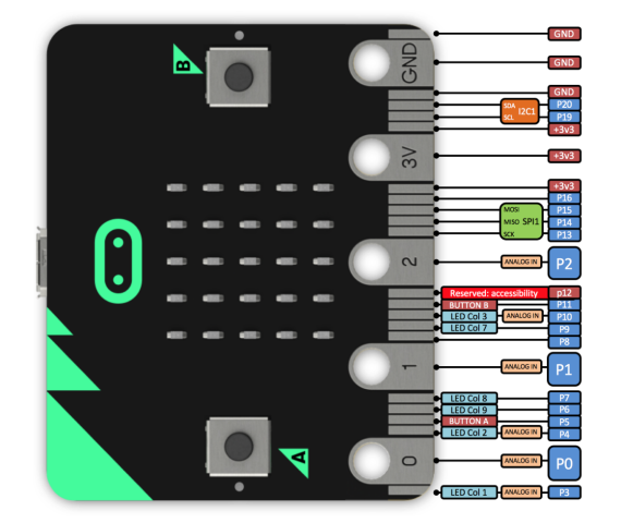
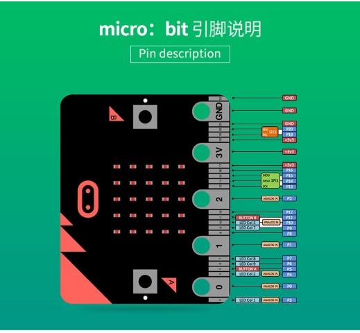
Micro:bit Pinout
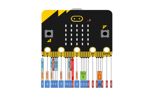
Micro:bit V2
Micro:bit V1.5
Official website:https://tech.microbit.org/hardware/edgeconnector/
https://microbit.org/guide/hardware/pins/
Note:
Put it on with silicone case to prevent the short circuit due to electronic components on micro:bit V2
b. Don’t interface V2 board with high current components(such as servo MG995, DC motor) because of its weak driving ability (less than 300mA)of IO port, otherwise, it will be burned out.
We recommend you to work with micro:bit expansion board before using it.
c. We supply power via USB port or 3V port of micro:bit V2. However, the micro:bit shield is needed if you use 5V sensor because its voltage is 3V.
d. Remember to disable(you can use this block to disable the
pin )the common pins of micro:bit
like P3, P4, P6, P7 and P10 in the code, otherwise, the data will be wrong.
)the common pins of micro:bit
like P3, P4, P6, P7 and P10 in the code, otherwise, the data will be wrong.
e. The battery above 3.3V is not allowed to be used, otherwise, micro:bit V2 will get damaged.
f. Don’t put it on the metal object to avoid short circuit.
To conclude, micro:bit V2 is like a mini computer.
Online coding website: https://microbit.org/code/
Kit list:
# |
Name |
QTY |
Picture |
|---|---|---|---|
1 |
Micro:bit Development Board |
1 |
|
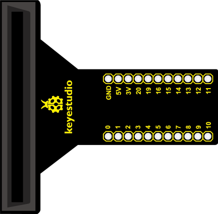
2 |
Keyestudio T-type Expansion Board |
1 |
|
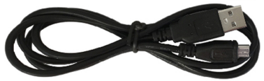
3 |
USB Cable |
1 |
|
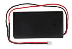
4 |
2-slot AA Battery Holder |
1 |
|
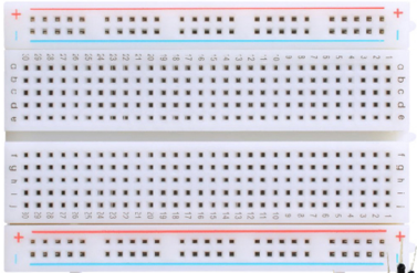
5 |
400 Holes Breadboard |
1 |
|
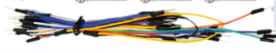
6 |
Breadboard Lead |
1 |
|
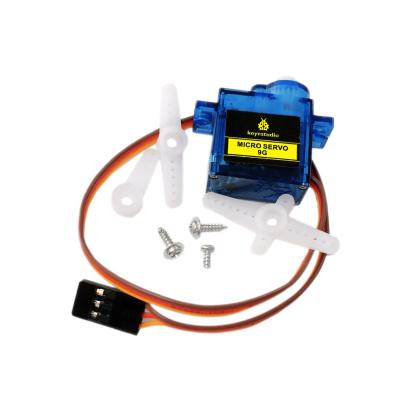
7 |
90°Keyestudio Servo |
1 |
|
8 |
1-digit Segment Display |
1 |
|
9 |
Passive Buzzer |
1 |
|
10 |
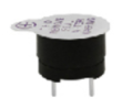
Active Buzzer |
1 |
|
11 |
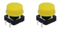
Push Button Sensor |
2 |
|
13 |
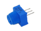
Adjustable Potentiometer |
1 |
|
14 |
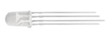
Common Cathode Full Color RGB |
1 |
|
15 |
LM35DZ Temperature Sensor |
1 |
|
16 |
5MM Photoresistor |
3 |
|
17 |
Thermistor Sensor |
1 |
|
18 |
Flame Sensor |
1 |
|
19 |
Ball Tilt Switch |
2 |
|
20 |
F5 Red LED |
5 |
|
21 |
F5 Yellow LED |
5 |
|
22 |
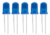
F5 Blue LED |
5 |
|
23 |
F5 Green LED |
5 |
|
24 |
220R Resistor |
10 |
|
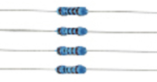
25 |
1K Resistor |
10 |
|
26 |
10K Resistor |
10 |
|
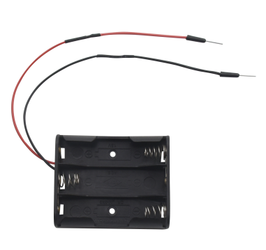
27 |
4.5V 3-slot AA Battery Holder |
1 |
|


Install the Driver of Micro:bit
The installation of driver wouldn’t be needed, if you already installed it.
But, you need to install driver if it’s your first use.
Download link: https://fs.keyestudio.com/KS0306-Driver
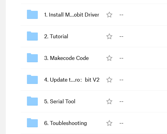
You can download driver file (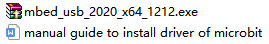 )
in the
)
in the  folder.
Programming:
We will take Windows system as example.
1 Quick Start:
This chapter introduces how to program and download code to micro:bit V2. There are detailed tutorials in the official website, as shown below:
https://microbit.org/guide/quick/
Step 1: Connect Micro:bit V2
Interface micro:bit V2 with your computer using USB cable. (Guide to mobile & tablet apps:https://microbit.org/get-started/user-guide/mobile/).
Macs , PCs, Chromebooks and Linux system(including Raspberry Pi)support micro:bit V2.
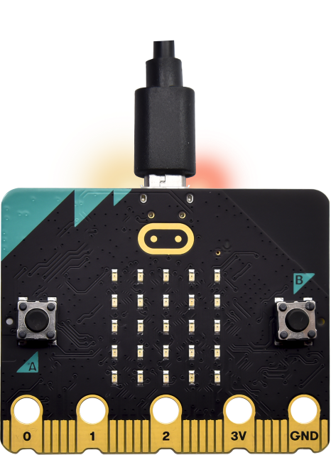
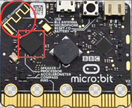
After board is connected to computer, a red LED at the back of micro:bit V2 will be on.
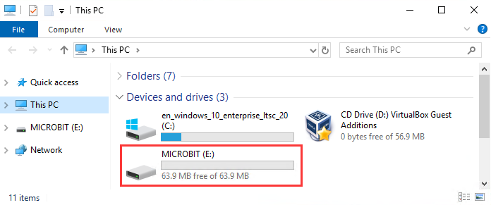
There will be a MICROBIT drive in your computer, as shown below:
Step 2: Programming:
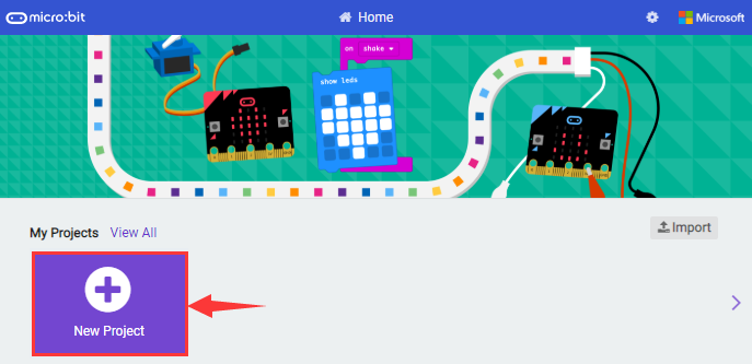
Enter https://makecode.microbit.org/ (we recommend you to use Google Chrome),
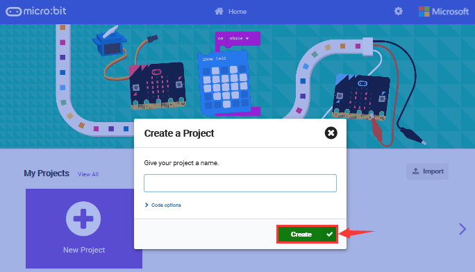
then click  and you will view a
dialog box.
and you will view a
dialog box.
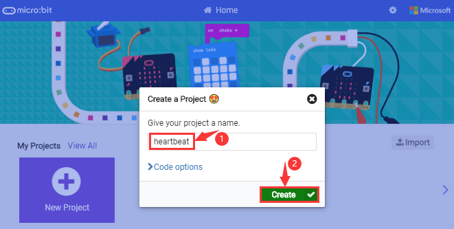
Input“heartbeat”to name your project and click“Create”.
What’s more, you can download Makecode app if your system is Windows 10: https://www.microsoft.com/zh-cn/p/makecode-for-micro-bit/9pjc7sv48lcx?ocid=badgep&rtc=1&activetab=pivot:overviewtab
Through MakeCode editor, you just need to drag blocks from block area into code editing area to program. Then run this code on simulator of makecode, as shown below:
We provide a guidance video in the test code folder(download test code in the link https://fs.keyestudio.com/KS0306
Step 3: Download Code:
The code can be directly downloaded to micro:bit V2 if you tap“Download”icon on makecode App.
However, follow the steps below if you program via online makecode editor.
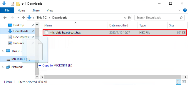
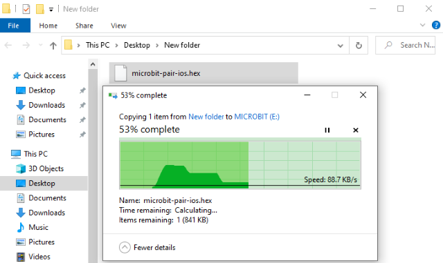
Enter online Makecode editor, tap“Download”to get a“hex”file. Then copy it into MICROBIT drive.
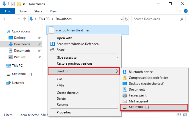
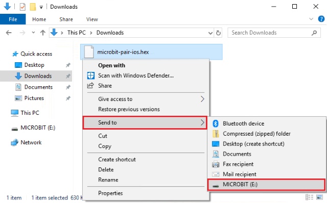
Or you can find out“hex”file firstly and right-click to select“Send to”MICROBIT(E)”.
Then hex file will be copied on MICROBIT drive.
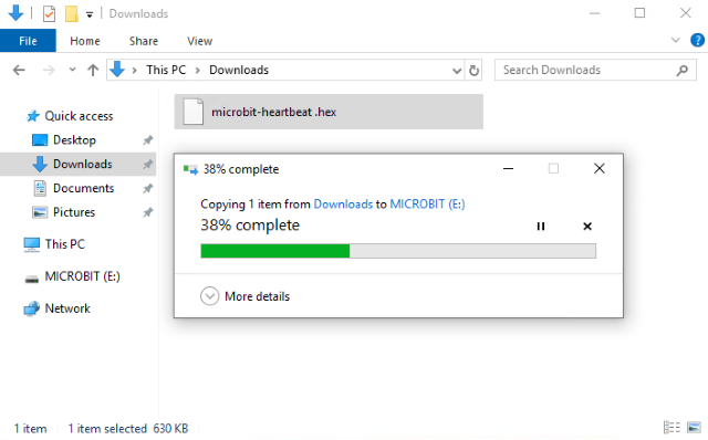
The yellow indicator will flash when transferring“hex” into micro:bit V2. And it is solid on after the file is copied.
Step 4: Run Program:
Download code to micro:bit V2 and connect micro:bit V2 to external power with USB cable.
5 x 5 LED will show heartbeat pattern.
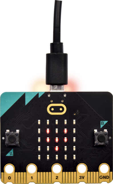 Power Supply—–micro USB
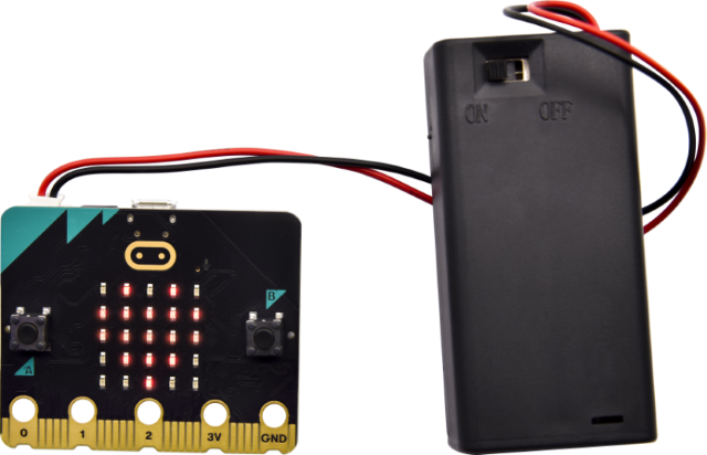 External Power(3V)
Step5:Acknowledge:
You can code in other ways:
2.Makecode:
Navigate https://makecode.microbit.org/ on Google Chrome, and enter online makecode editor. Or you can open makecode app for Windows 10.
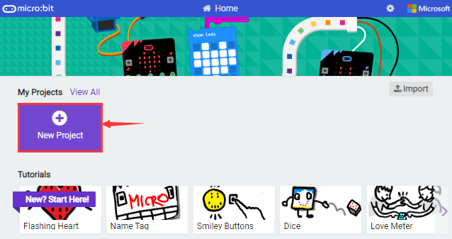
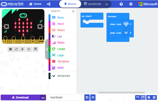
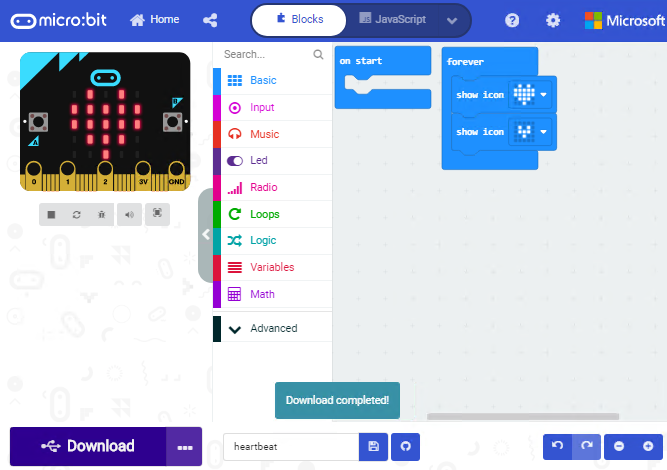
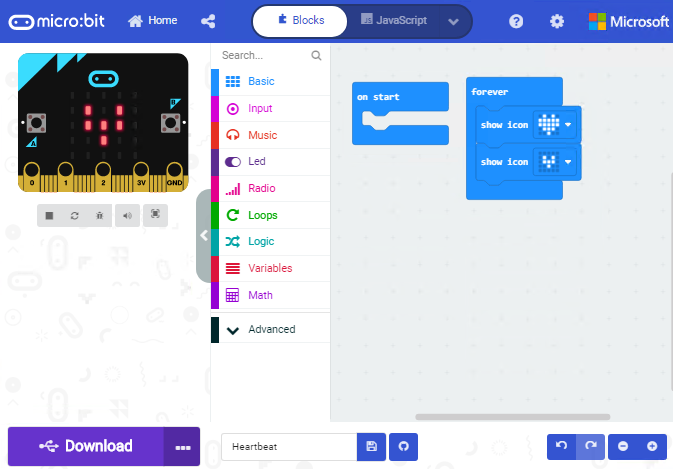
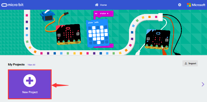
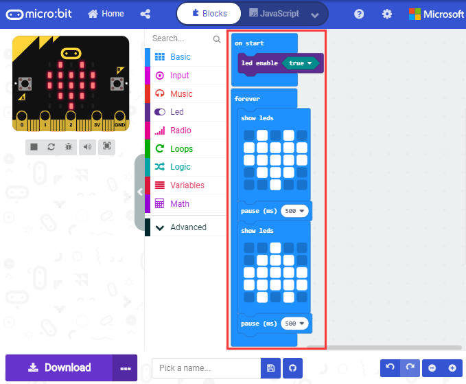
Click“New Project”, input“heartbeat”, click“Create”and enter Makecode editor, as shown below:
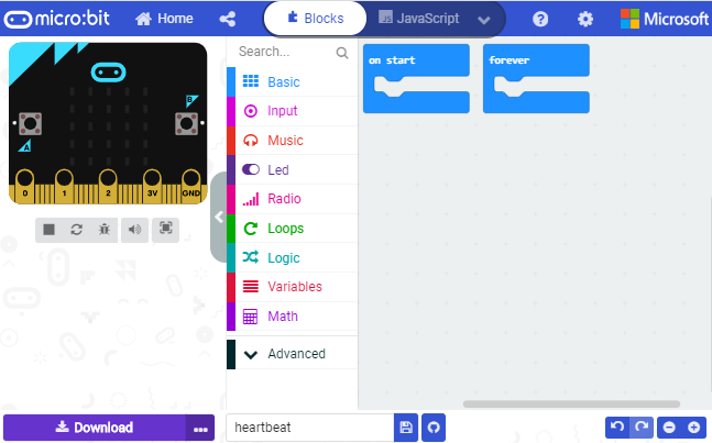
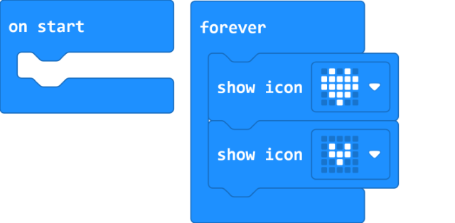
There are block“on start”and“forever”in the code editing area.
After power on or reset,“on start”block means that command blocks in the code are only run once, however,“forever”implies that code runs cyclically.
3. Quick Download:
You can click“download”to transfer code to micro:bit V2 if you use makecode App for Windows 10.
Whereas, the online Makecode editor requires intricate steps.
Operating Google Chrome on Android, ChromeOS, Linux, macOS or Windows 10 system, you can achieve the quick download.
We use the webUSB function of Chrome to allow the internet page to access the hardware device connected USB.
You can refer to the following steps to connect and pair device.
Pairing Device:
Interface micro:bit V2 with computer using USB cable.
Click“…”beside“Download”and tap“Pair device”.
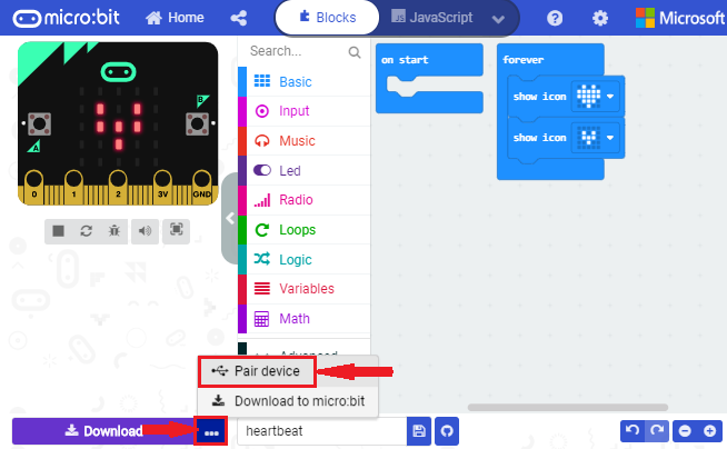
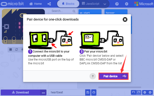
Continue to tap“Pair device”
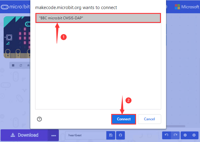
Then select the device you want to connect and tap“connect”in the window .
If there is no device in the window, please refer to the following link:
https://makecode.microbit.org/device/usb/webusb/troubleshoot
We also provide  in the resource
link.
in the resource
link.
What’s more, if you don’t know how to update the firmware of micro:bit, refer to
the link:
https://microbit.org/guide/firmware/
or browse folder we provide.
After connecting successfully, press buttons and download code to micro:bit V2.
4. Resource:
https://fs.keyestudio.com/KS0306
5. Import Code:
We provide every program with a hex file. You can import it directly or program in Makecode blocks area
Next, we will take“heartbeat”as example to introduce how to import code.
Open online Makecode editor or Makecode App.
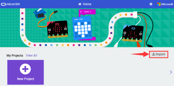
Tap“import”and“Import File”
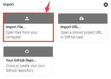
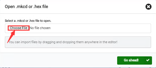
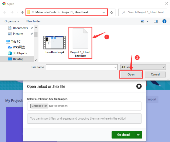
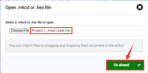
Choose file“../Makecode Code/Project 1_ Heart beat/Project 1_ Heart beat.hex”, then tap“Go ahead”
In addition to the above method of importing code, you can also directly drag code into the Makecode compiler, as shown in the figure below:
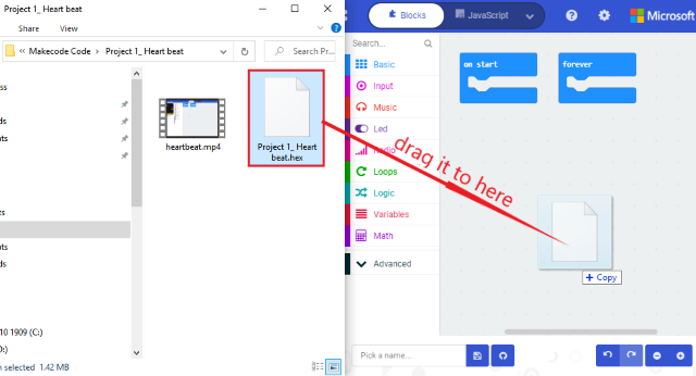
The program is imported successfully after a few seconds.
If your computer system is Windows7/8 instead of Windows 10, the device can’t be paired in Google Chrome, as a result, the digital and analog signals can’t be read.
Here, we need CoolTerm software to read data.
For the whole projects, we will use CoolTerm software.
Let’s install it firstly.
6. Install CoolTerm:
CoolTerm program is used to read the serial communication.
Download CoolTerm program:
https://freeware.the-meiers.org/
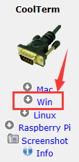
After the download, we need to install CoolTerm Win, and we take example of the Window system
Choose“win”
Unzip file and open it. (also suitable for Mac and Linux system)
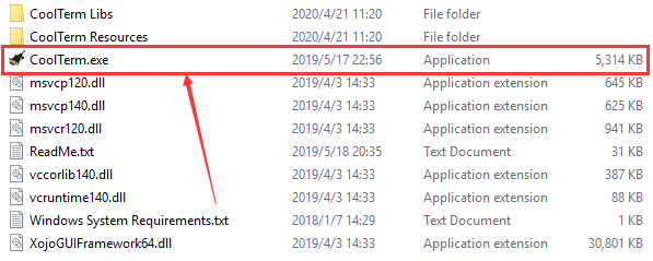
Double-click
Note: Firstly, you have to install the driver of micro:bit and connect micro:bit V2 to computer.
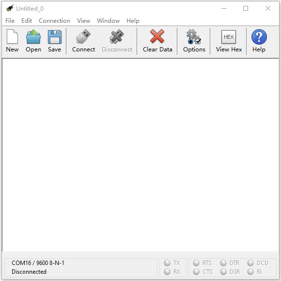
The functions of each button on the toolbar are listed below: http://wiki.keyestudio.com/index.php/File:IDE.png

|
Opens up a new Terminal |
|---|---|
|
Opens a saved Connection |
|
Saves the current Connection to disk |
|
Opens the Serial Connection |
|
Closes the Serial Connection |
|
Clears the Received Data |
|
Opens the Connection Options Dialog |
|
Displays the Terminal Data in Hexadecimal Format |
|
Displays the Help Window |


Projects:
Project 1: Heartbeat
Description:
Prepare a Micro:bit V2, a USB cable and a computer. Next we will conduct a basic experiment that a heartbeat pattern flashes on micro:bit board.
Components:
Micro:bit V2 *1
Micro USB Cable*1
3. Wiring Up:
Interface micro:bit V2 with your computer using micro USB cable.
4. Example Code
You can enter this website https://makecode.micro:bit.org/reference to get more information even you’re a starter.
Edit your code in the link: https://makecode.micro:bit.org/
5. Test Result
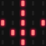
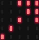
Download code to micro:bit V2 (refer to chapter 4.1), and keep micro USB cable
connected. Then image“❤”and“ ”will
be shown on micro:bit ceaselessly.
”will
be shown on micro:bit ceaselessly.
If download unsuccessfully, disconnect micro:bit V2 and reboot it please.
Then download code to V2 board again
Project 2: Light Up A Single LED
Description:
In this project, we will turn on an LED of micro:bit V2.
Components:
Micro:bit V2 *1
Micro USB Cable*1
3. Wiring Up:
Interface micro:bit V2 with your computer using micro USB cable.
4. Component Overview:
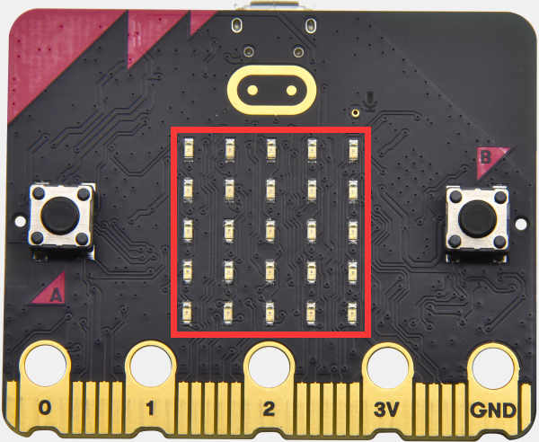
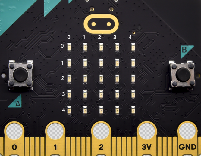
Micro:bit V2 consists of 25 light-emitting diodes, 5 pcs in a group. They correspond to x and y axis. Then the 5*5 matrix is formed. Moreover, every diode locates at the point of x and y axis.
Virtually, we can control an LED by setting coordinate points. For instance, set coordinate point(0,0)to turn on the LED at row 1 and column 1; light up LED at the row 1 and column 3, we can set(2,0) and so on.
5.Example Code
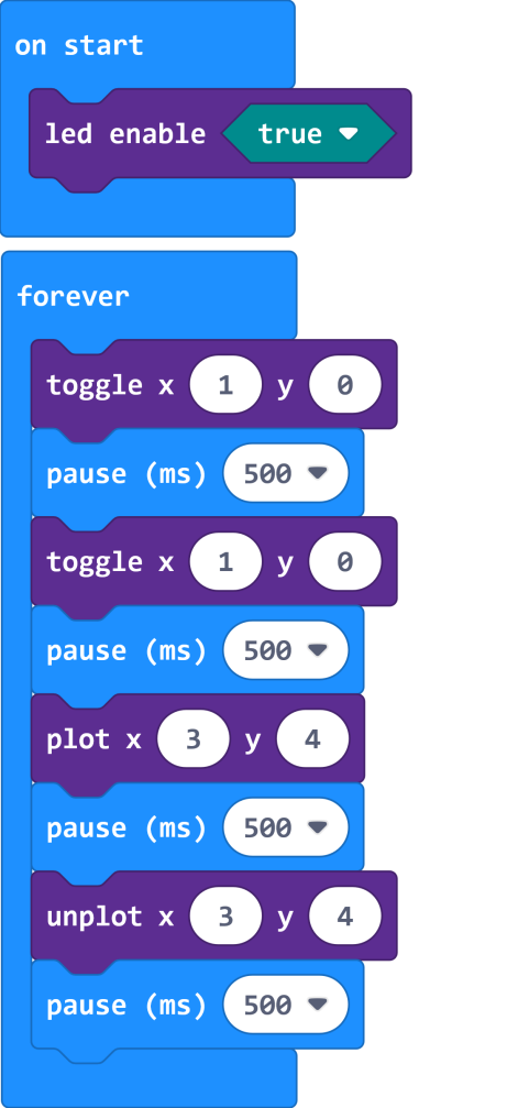
Test Result
Download code to micro:bit V2 and connect it to computer with USB cable. As a result, the LED at coordinate point (1,0) flashes for 1 s and the LED at (3,4)blinks for 1s, alternately.
Project 3: 5 x 5 LED Dot Matrix
Description:
Dot matrix gains popularity in our life, such as LED screen, bus station and the mini TV in the lift.
The dot matrix of Micro:bit board consists of 25 light emitting diodes. In previous lesson, we control LED of Micro:bit board to form patterns, numbers and character strings by setting the coordinate points. Moreover, we could adopt another way to complete the display of patterns, numbers and character strings.
Components:
Micro:bit V2 *1
Micro USB Cable*1
3. Wiring Up:
Interface micro:bit V2 with your computer using micro USB cable.
4.Example Code
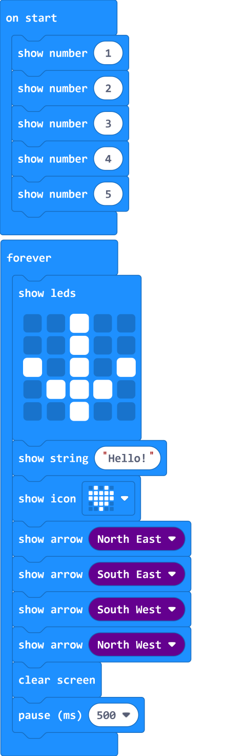
5. Test Result
Download code to micro:bit V2, and and keep USB cable connected. Micro:bit V2
will display 1, 2, 3, 4 and 5 and separately show
 icon,
icon,
“Hello!”,  ,
,
 ,
,
 ,
,
 and
and
 patterns.
Project 4: Programmable Buttons
Description:
The circuit is controlled by button. The circuit is connected when the button is pressed; however, the circuit is disconnected when released.
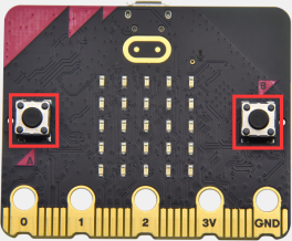
Micro:bit V2 has three buttons which are the reset button on the back and two programmable buttons(A, B) on the front. Next, let’s conduct experiment to know how button works.
2. Components:
Micro:bit V2 *1
Micro USB Cable*1
3. Wiring Up:
Interface micro:bit V2 with your computer using micro USB cable.
4. Example Code 1:
Test Result 1:
Download code to micro:bit V2 and keep USB cable connected.
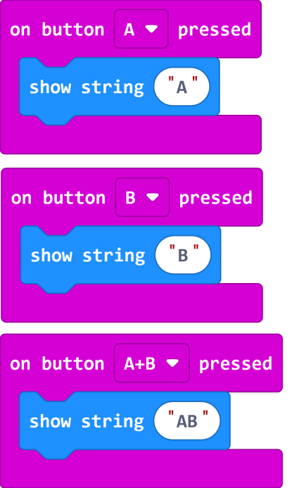
5×5 LED dot matrix will show the corresponding letter if the button A or B is pressed. In other words, the micro:bit V2 will also show“AB”if you press A and B buttons simultaneously.
6. Example Code 2:
7. Test Result 2:
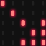
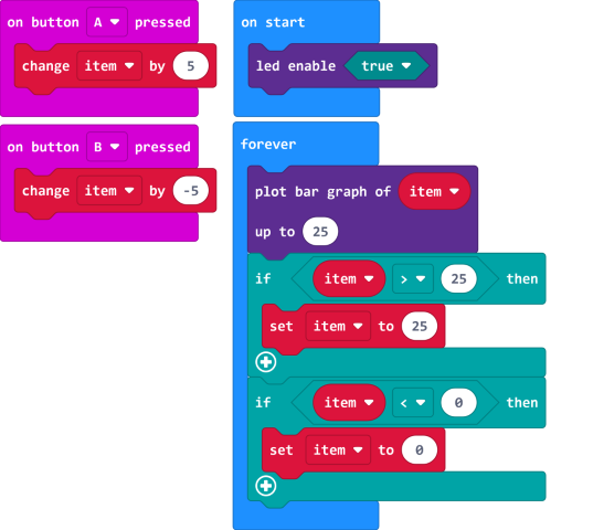
Download code to micro:bit V2 and keep USB cable connected. A row of luminous LEDs are added if button A is pressed; and when B is pressed, a row of luminous LEDs are deducted.
Project 5: Temperature Measurement
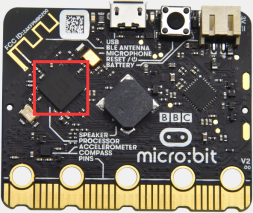
Description:
We will introduce how to detect ambient temperature by micro:bit V2. Its detection range is -40℃~105℃.
2. Components:
Micro:bit V2 *1
Micro USB Cable*1
3. Wiring Up:
Interface micro:bit V2 with
your computer using micro USB cable.
4.Example Code
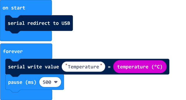
5. Test Result
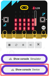
Download code to micro:bit V2 and plug in power with USB cable. Then click“Show console Device”button.
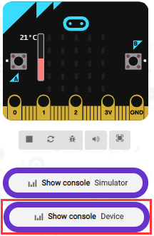
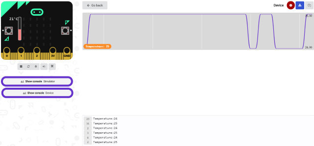
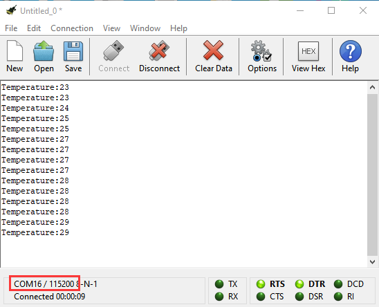
Open serial interface to check temperature value, as shown below:
If your computer system is Windows7/8 instead of Windows 10, the device can’t be paired in Google Chrome, as a result, the digital and analog signals can’t be read.
Here, we need CoolTerm software to read data.
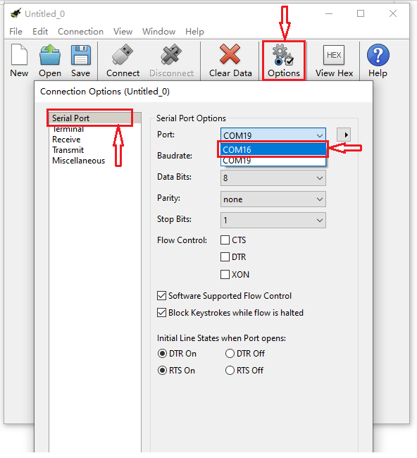
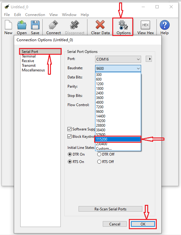
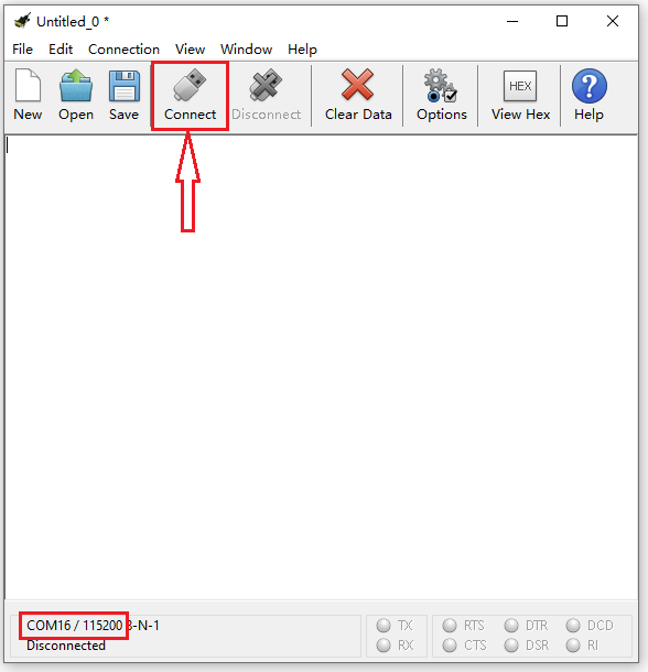
Open CoolTerm, click“Options”to select“SerialPort”. Set COM port and 115200 baud rate(the baud rate of USB serial communication of micro:bit V2 is 115200 through the test). And click“OK”and“Connect”.
The serial monitor shows the current ambient temperature value, as shown below:
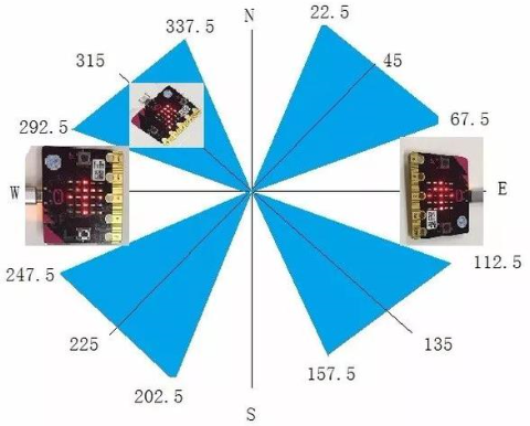
Project 6: Micro:bit’s Compass
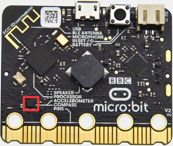
Description:
This project mainly introduces the use of the Micro:bit’s compass. In addition
to detecting the strength of the magnetic field, it can also be used to
determine the direction, an important part of the heading and attitude reference
system (AHRS) as well.
It uses LSM303AGR three-axis magnetometer whose the range of magnetic field is
±50 gauss. In this project, we will introduce how compass detect data and
determine direction.
Then we can read the value detected by it to determine the location. We need to calibrate the micro:bit V2 when magnetic sensor works.
Components:
Micro:bit V2 *1
Micro USB Cable*1
3. Wiring Up:
Interface micro:bit V2 with your computer using micro USB cable.
4. Example Code1:
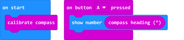
5. Test Result1:
Download code to micro:bit V2 and keep USB connected.
As the button A is pressed, LED dot matrix indicates that“TILT TO FILL SCREEN”then enter the calibration interface.
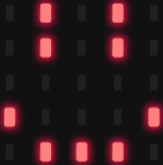
The calibration method: rotate the micro:bit V2 to make LED dot matrix display a full square (25 LEDs are on), as shown in the following figure:
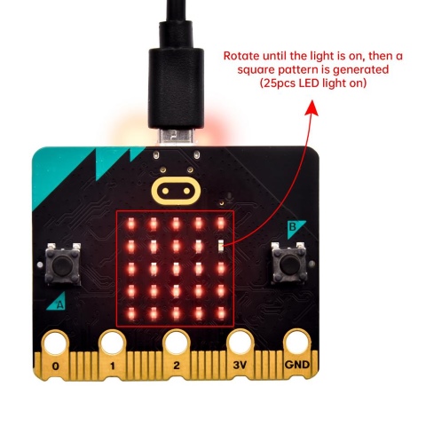
The calibration won’t be finished until you view the smile pattern
 appear.
The serial monitor will show 0°, 90°, 180° and 270° when button A is pressed.
6. Example Code2:
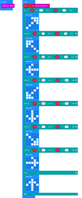
This block implies that the value is read ceaselessly and the arrow direction is North.
The micro:bit V2 shows the  icon,
if the value is between 292.5 and 337.5. The value should be 293 and 338 because
decimal is not allowed to be filled in the code.
icon,
if the value is between 292.5 and 337.5. The value should be 293 and 338 because
decimal is not allowed to be filled in the code.
Complete Example Code2:
Test Result2:
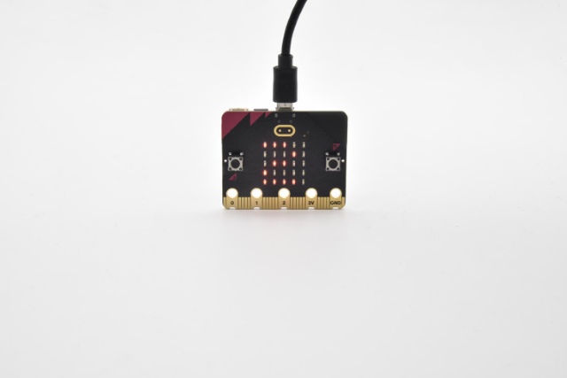
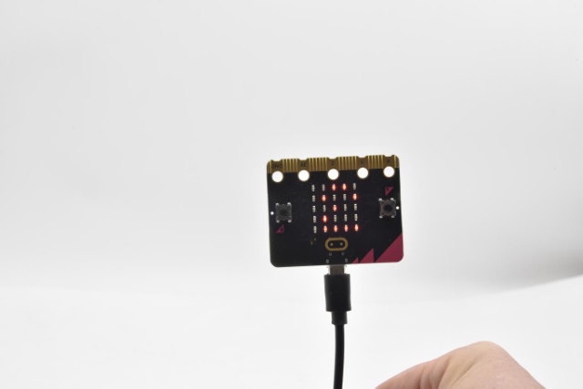
Download code to micro:bit V2 and keep USB cable connected.
After the calibration(see the result1) and tilt micro:bit V2, then the direction signs will be shown.
Project 7: Accelerometer
Description:
The micro:bit V2 has a built-in LSM303AGR three-axis acceleration sensor (accelerometer). Its I2C interface works on external communication, the range can be set to 1g, 2g, 4g and 8g.
We usually detect the posture of accelerometer.
In this project, we will check the value detected by accelerometer.
Components:
Micro:bit V2 *1
Micro USB Cable*1
3. Wiring Up:
Interface micro:bit V2 with your computer using micro USB cable.
Example Code1:

Test Result 1:
Download code to micro:bit V2 and keep USB cable connected.
Micro:bit V2 will display“1”if shaken.
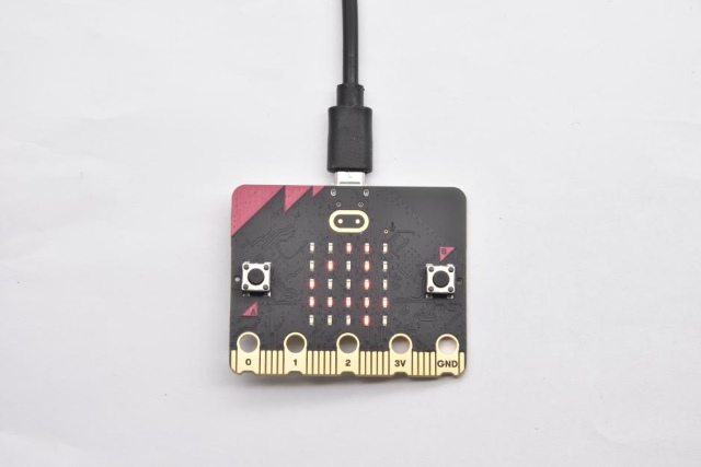
Place micro:bit V2 vertically(logo up), then the number 2 is displayed:
Place micro:bit V2 vertically(logo down), then the number 3 is displayed:
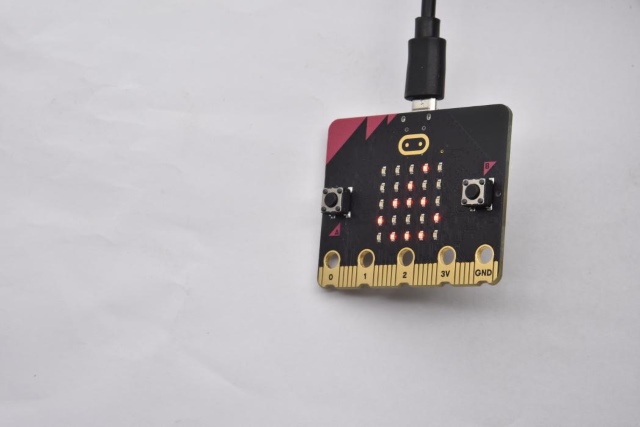
Place micro:bit V2 horizontally (facing up), then the number 4 is displayed:
On the contrary, place micro:bit V2 horizontally (facing down), then the number 5 is displayed:
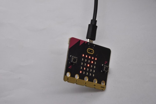
When Micro:bit board is tilt to the left, number 6 is shown.
When Micro:bit board is inclined to the right, number 7 is displayed.
When it is free fall(accidentally making it fall), number 8 will appear on dot matrix.(Note:we don’t recommend you to make it free fall, it will make board damage)
6. Example Code2:
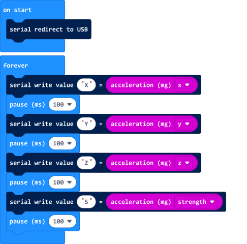
7. Test Result2:
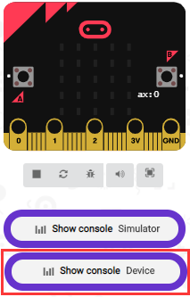
Download code to micro:bit V2, keep USB cable connected, and click “Show Console Device”
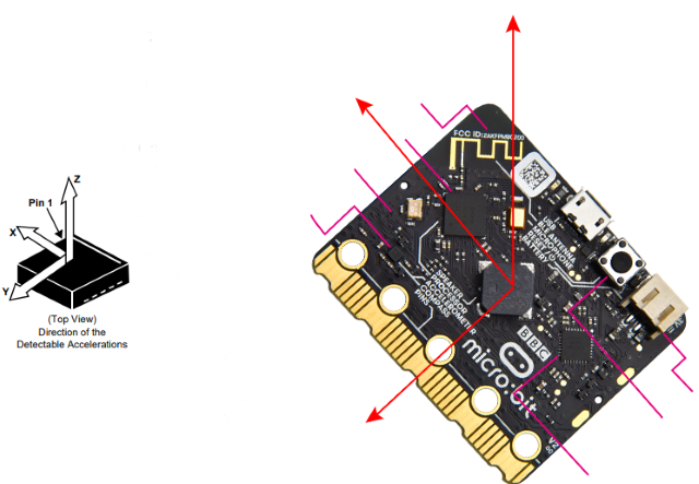
According to MMA8653FC manual, the acceleration coordinates of the accelerometer are shown in the following figure:
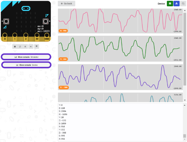
The decomposition value of acceleration on the X-axis, Y-axis, and Z-axis, and the synthesis value of acceleration (the synthesis of gravitational acceleration and other external forces) are shown below:
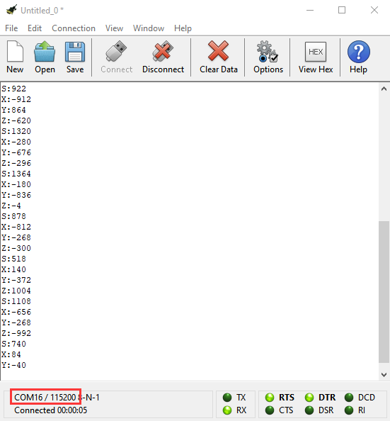
If your computer system is Windows7/8 instead of Windows 10, the device won’t be paired in Google Chrome.
Here, we need CoolTerm software to read data.
Open CoolTerm, click“Options”to select“SerialPort”.
Set“COM”port and 115200 baud rate(the baud rate of USB serial communication of Micro:bit is 115200 through the test).
Click“OK”and“Connect”.
CoolTerm serial monitor displays the acceleration value on x, y and z axis, as shown below:
Project 8: Detect Light Intensity by Micro:bit
Description:
This project will introduce how micro:bit V2 detects the external light intensity. Since micro:bit doesn’t come with photosensitive sensor, the detection of light intensity is completed through the LED matrix. When the light irradiates the LED matrix, the voltage change will be produced. Therefore, we could determine the light intensity by voltage change.
Components:
Micro:bit V2 *1
Micro USB Cable*1
3. Wiring Up:
Interface micro:bit V2 with your computer using micro USB cable
4.Example Code
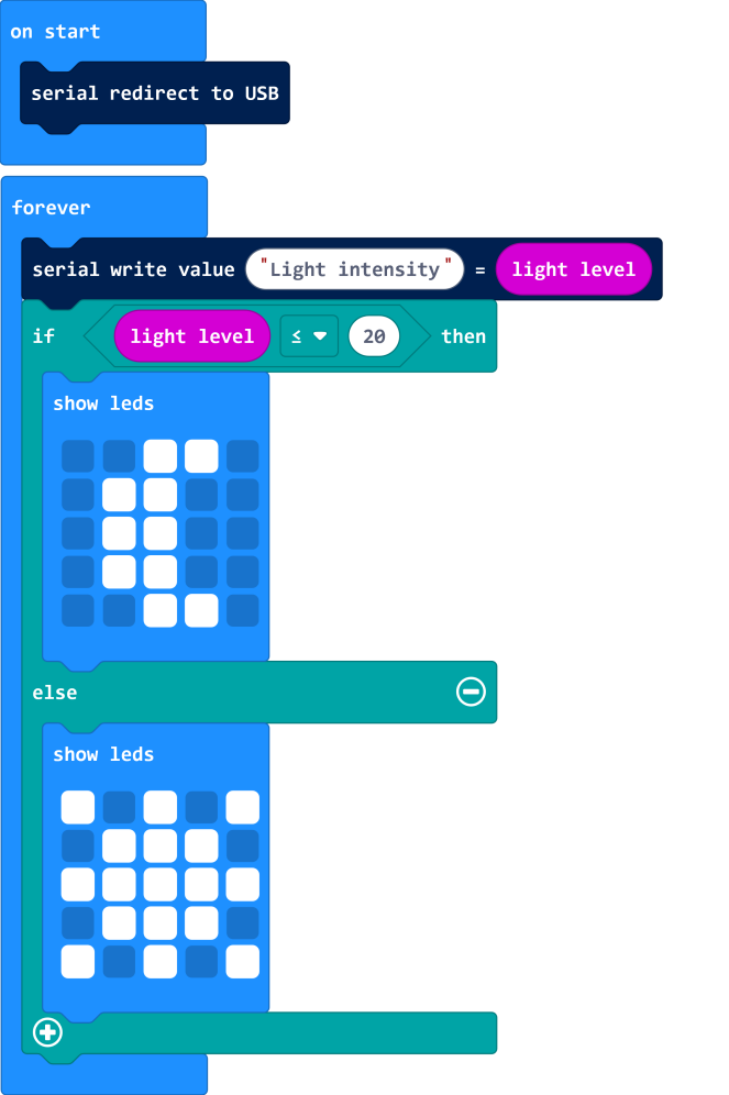
Test Result
Download code to micro:bit V2, keep USB cable connected, and click “Show Console Device”
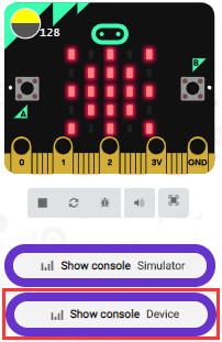
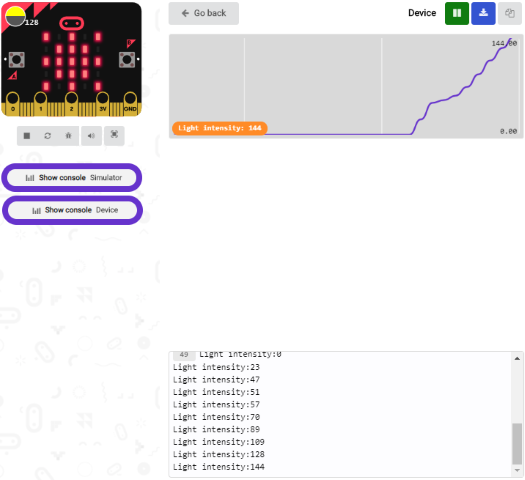
The intensity value is about 0 when covering LED dot matrix. And the value varies with the light intensity. When placing micro:bit V2 under the sunlight, the stronger the light is, and the larger the intensity value will be. As shown below:
Number 20 in the code is a random light intensity value we set. Micro:bit V2 will show“moon”picture when the light intensity is less than or equivalent to 20; however, the “sun”image will appear if the value is more than 20.
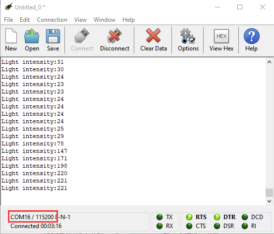
If your computer system is Windows7/8 instead of Windows 10, the device can’t be paired in Google Chrom.
Here, we need CoolTerm software to read data.
Open“CoolTerm”, click“Options”to select“SerialPort”, and set “COM” port and 115200 baud rate(the baud rate of USB serial communication of micro:bit V2 is 115200 through the test).
Then click“OK”and“Connect”.
The light intensity value is shown below:
Project 9: Speaker
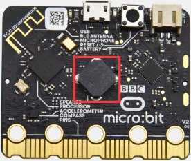
Description:
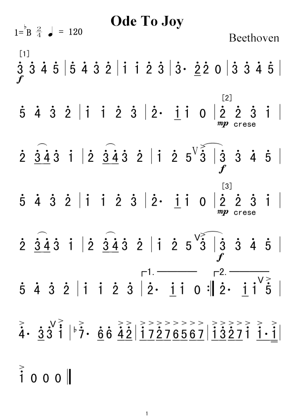
The micro:bit V2 has built-in speaker for emitting different tones. You can composite a song like“Ode to Joy”and other beautiful songs.
Components:
Micro:bit V2 *1
Micro USB Cable*1
Wiring Up:
Interface micro:bit V2 with your computer using micro USB cable.
4. Test Code1:
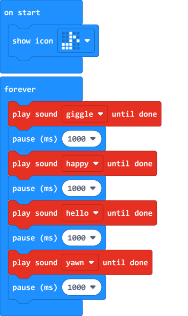
5. Test Result 1:
Download code to micro:bit V2 and plug in power with USB cable.
Then micro:bit V2 shows music icon and emits sound.
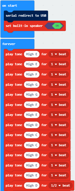
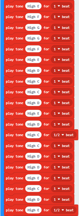
Test Code 2:
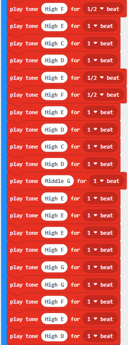
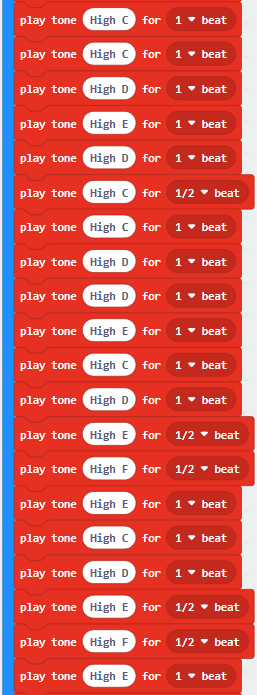
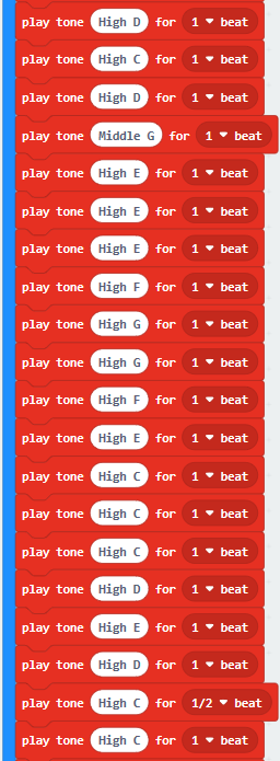
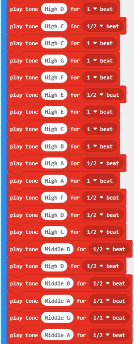
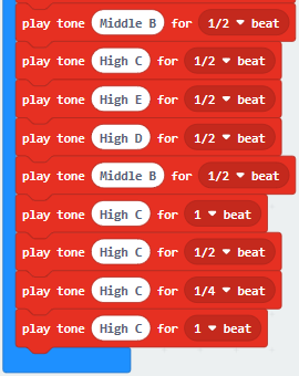
More resource:
https://en.wikipedia.org/wiki/Numbered_musical_notation
Test Result 2:
Download code to micro:bit V2 and plug in power with USB cable, as a result, micro:bit V2 emits song“Ode to Joy”.
Project 10: Touch Sensitive Logo
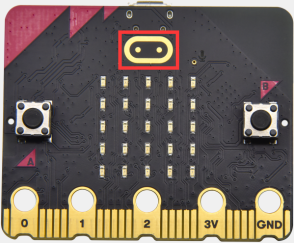
Description:
Micro:bit V2 has a touch sensitive logo as a input. It is fundamentally a capacitive touch sensor which can sense the tiny changes in the current.
Components:
Micro:bit V2 *1
Micro USB Cable*1
3. Wiring Up:
Connect micro:bit V2 to your computer with micro USB cable.
4. Example Code
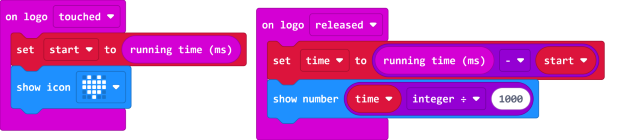
5. Test Result
Download code to micro:bit and connect it to power. Then if the logo of micro:bit pressed, you will find“❤”appear on micro:bit; yet, if not pressed, the number will be shown on micro:bit.
6. Test Result:
Download code to micro:bit V2 and keep USB cable connected.
Micro:bit V2 will show“❤”if you touch logo
 , on the contrary, the number
will be shown if the log is not
touched.
, on the contrary, the number
will be shown if the log is not
touched.
Project 11: Microphone
Description:
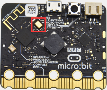
The micro:bit V2 has a built-in microphone which can detect the sound intensity.
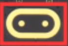
The microphone LED indicator in the front of micro:bit V2 will be turned on if you clap your hands, therefore, we can make an analog noise level watch or display a disco light effect.
2. Components:
Micro:bit V2 *1
Micro USB Cable*1
3. Wiring Up:
Interface micro:bit V2 with your computer using micro USB cable.
4. Test Code1:
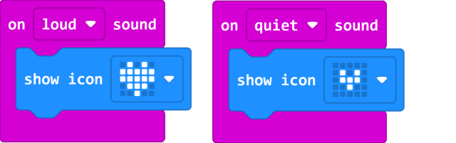
5. Test Result1:
Download code to micro:bit V2, and keep micro USB connected. Pattern“❤”will be
displayed when you clap your hands; however,
pattern“”will appear when in the
quit environment.
Example Code 2:
7. Test Result 2:
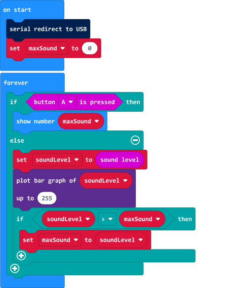
Download code to micro:bit V2 and keep micro USB cable connected. Click“Show console device”.
The output sound value will increase when the sound amplifies, as shown below;
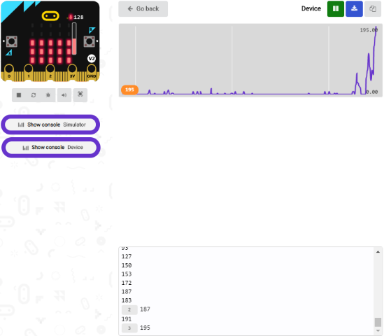
Micro:bit V2 will show the maximum value of sound intensity value(Note: set the maximum value via reset button), when button A is pressed; whereas, the sound level icon will be shown when clapping your hands.
Project 12: Read Bluetooth Data
Description:
The micro:bit V2 comes with a nRF52833 processor, a low consumption BLE device(Bluetooth 5.1) and 2.4GHz ethernet cable, communicating via Bluetooth wireless and 2.4GHz communication. In addition, V2 board can communicate with other Bluetooth devices like smart phones and computers.
In this experiment, we make micro:bit V2 play a role of Bluetooth wireless communication by interfacing it with a device.
Preparation:
Interface micro:bit V2 with computer using USB cable.
A cellphone or iPad
Steps
(1) For iOS system.
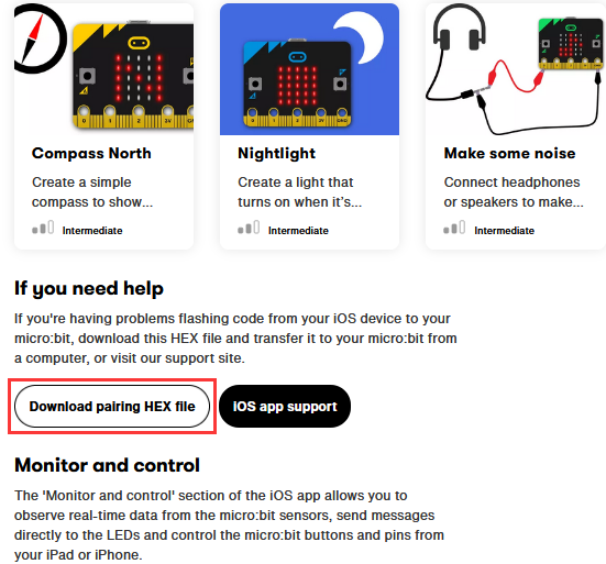
Navigate website:https://www.microbit.org/get-started/user-guide/ble-ios/, click“Download pairing HEX file”to download it in the folder or desktop of your PC and transfer to micro:bit V2.
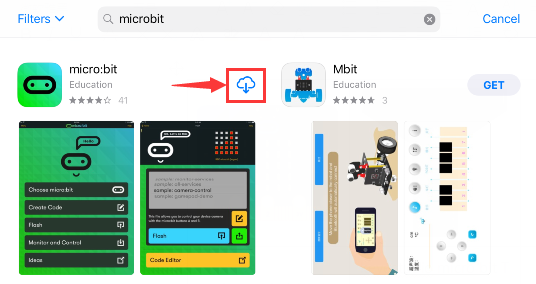
a. Open App Store

b. Search micro:bit and
click“ ”icon to download
c. Pair your device with micro:bit V2
d. Turn on the Bluetooth of your device
e. Make sure micro:bit is interfaced with your computer.
f. After the installation, click  and select“Choose micro:bit”to pair Bluetooth.
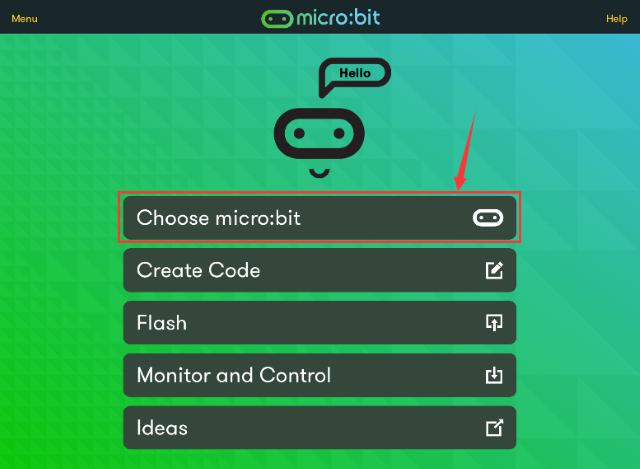
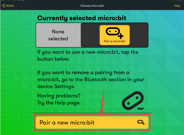
g. Select“Choose micro:bit”and click “Pair a new micro:bit”.
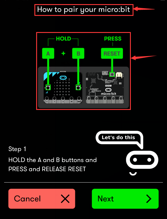
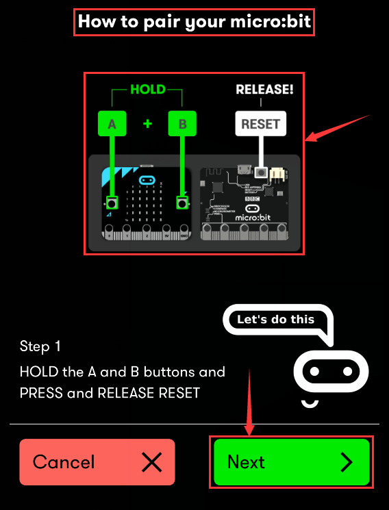
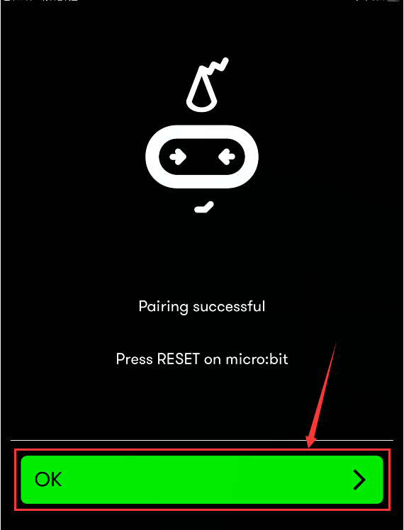
h. Press and hold button A and B simultaneously, then press and release the reset/power button. LED dot matrix will show a password image. At last, release the button A and B at same time and click“Next”.
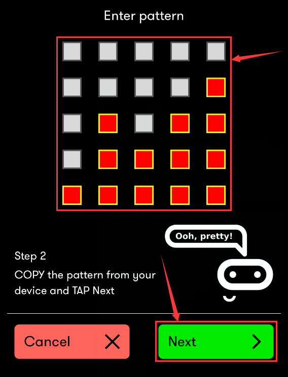
i. Next, design the password image on your device, and make password image as same as micro:bit V2.
J. Click“Next”.
k. Then click“Next”and“Pair”. After a few seconds, micro:bit V2 will show“√”pattern if the pairing is successful.
l. Then edit code on app and upload it
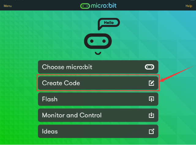
m. Tap“Create Code”to enter the programming page.
(Click , appear dialog
box
, appear dialog
box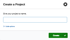 ,and select “Create √”)
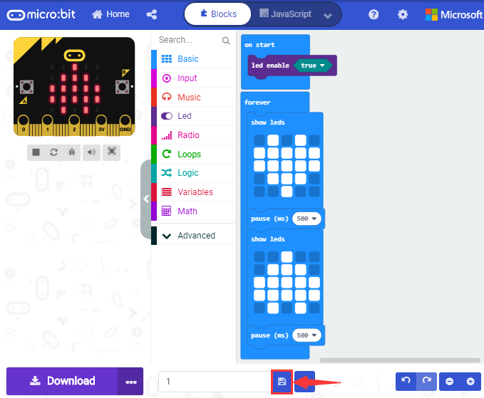
Name your program and click“ ” to
save it. We name“1”for this program.
” to
save it. We name“1”for this program.
After the code is saved, click“Flash”and select program 1.
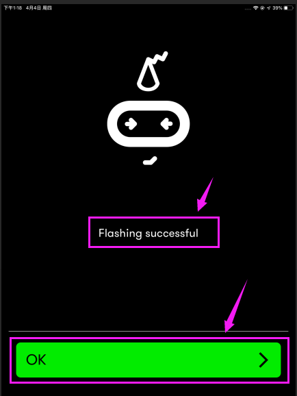
Next, tap“Flash”to transfer program 1 to micro:bit V2.
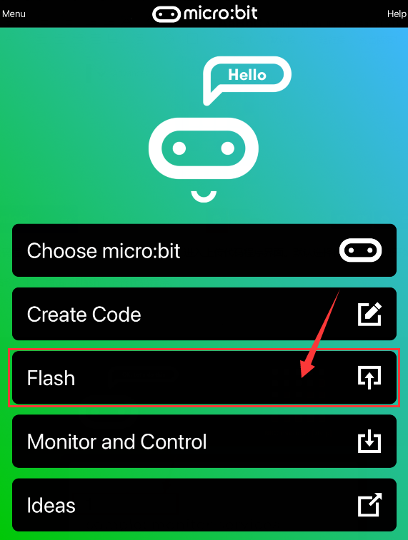
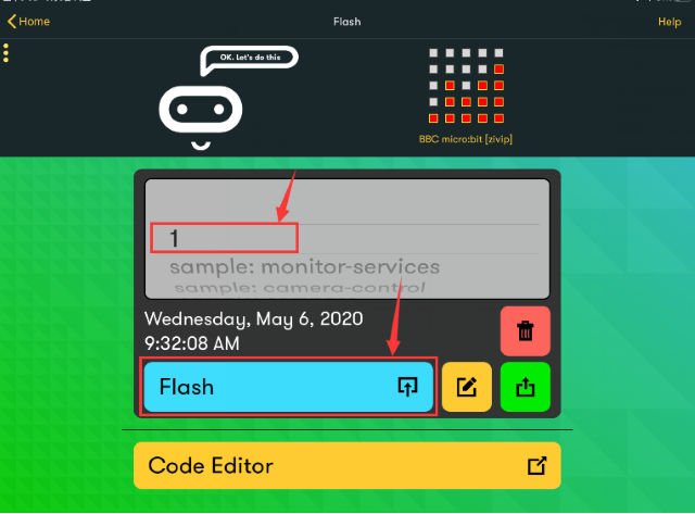
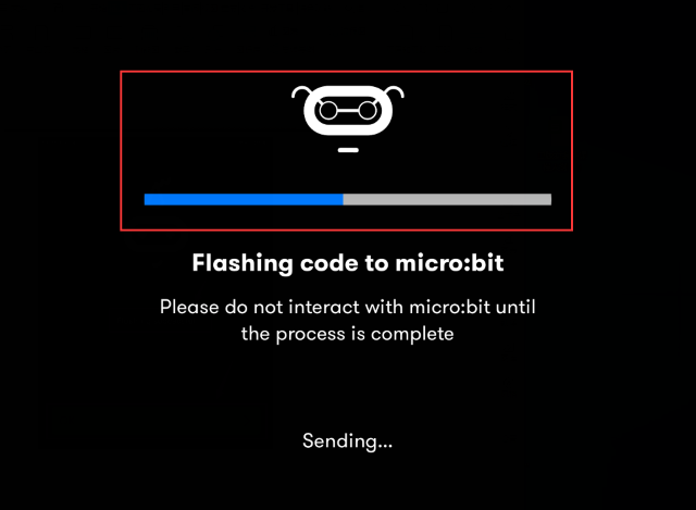
Micro:bit V2 will show the“Heartbeat”pattern if flashing is successful.
Project: 13: Flashing LED
Description
The experiment that flashes LED on and off is pretty simple and basic. In general, we control LED via 5 x 5 LED dot matrix on micro:bit. In this chapter, we will make LED blink.
Parts Required
Micro: bit*1
micro bit T-type Shield *1
USB Cable*1
LED*1
220Ω Resistor*1
Breadboard*1
Breadboard Wires
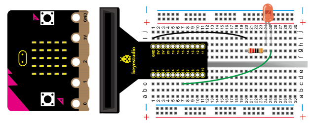
Hooking Up
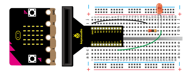
Test Code
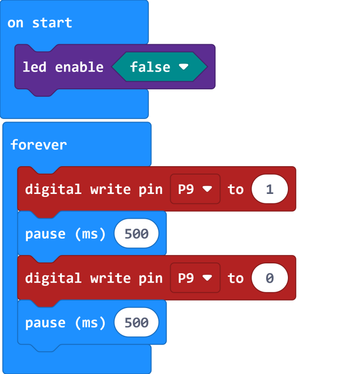
Test Result
Download code, plug in power and LEDs attached to IO port blink ceaselessly, with the interval of 0.5s
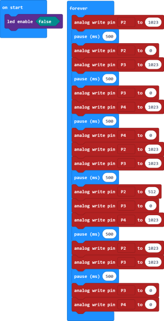
Project 14 Advertising Light
Description
The advertising light is everywhere in our daily life. It shows different information like words, slogans and images. Do you want to create your adverting light? This experiment will simulates advertising light effect.
Parts Required
Micro: bit*1
micro bit T-type Shield *1
USB Cable*1
LED*5
220Ω Resistor*5
Breadboard*1
Breadboard Wires
Hooking Up
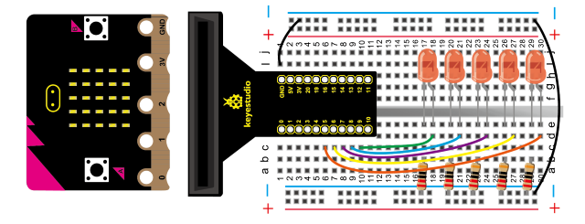
Test Code
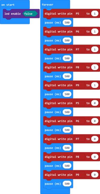
Test Result
Download code, plug in power and LEDs connected to IO port gradually get bright then dark one by one.
Project 15 Button-controlled LED
Description
Micro:bit has three buttons, two of which are button A and B in the front and one reset button. In this project, we will control LED on and off via button A or B.
Parts Required
Micro:bit*1
Micro:bit T-type Expansion Board *1
USB Cable*1
LED*1
220Ω Resistor*1
Breadboard*1
Breadboard Wires
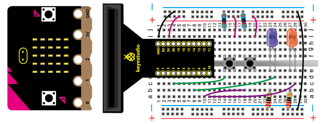
Hooking Up
Test Code
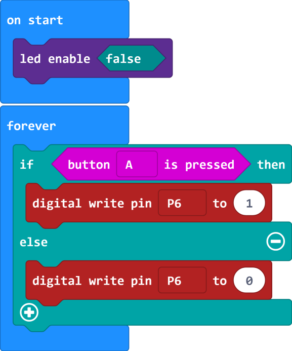
Test Result
Download code and plug in power firstly.
LED will be on if button A on micro:bit is pressed, otherwise, it will be off.
Project 16 Responder
1. Description
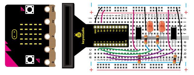
In the previous experiment, LED is controlled by buttons of micro:bit. In this lesson, we will teach you how to make a responder. Simultaneously, the two push buttons and a button of micro:bit are used to control the two LEDs
Parts Required
Micro:bit *1
micro bit T-type Shield *1
USB Cable*1
LED*2
Push Button*2
220Ω Resistor*2
10KΩ Resistor*2
Breadboard*1
Breadboard Wires
Hooking Up
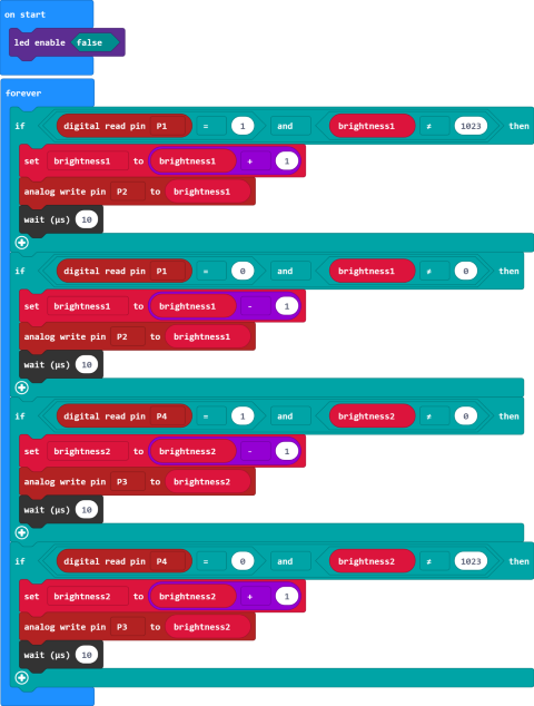
Test Code
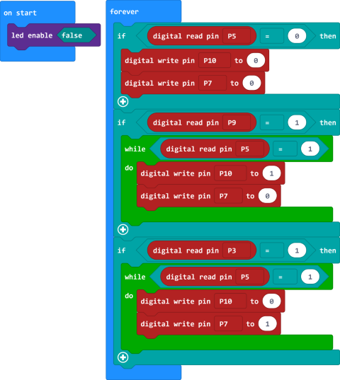
Test Result
Download code and plug in power firstly. The color of LED decides who the winner is.
And the two LEDs will be off when button A is pressed.
Project 17 Breathing LED
Description
We’ve known how to control LED on and off. Now, in this chapter, we will make LED effect simulate human breath.
Parts Required
Micro:bit*1
Micro:bit T-type Expansion Board *1
USB Cable*1
LED*1
220Ω Resistor*1
Breadboard*1
Breadboard Wires
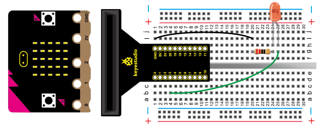
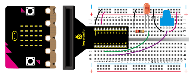
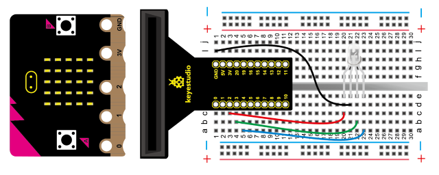
Hooking Up
Test Code
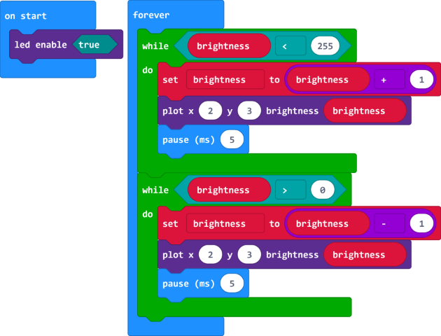
External LED
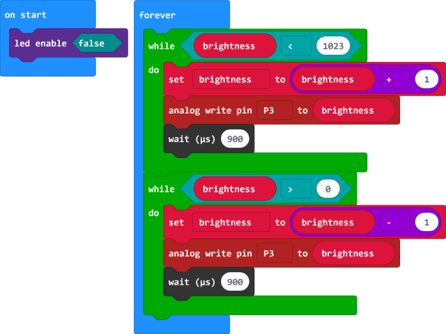
Test Result
Download code, plug in power and LED’s brightness smoothly changes from dark to bright and back to dark, continuing to do so and giving the illusion of an LED“breathing.”
Project 18 Adjust Light Brightness
Description
In this project, we will adjust LED brightness via potentiometer.
Remember to connect the ports of LED and potentiometer to analog ports.
Parts Required
Micro:bit Board*1
Micro bit T-type Expansion Board *1
USB Cable*1
LED*1
220Ω Resistor*1
Adjustable Potentiometer*1
Breadboard*1
Breadboard Wires
Hooking Up
Test Code

Test Result
Transfer code to micro:bit, plug in power and adjust the LED brightness by rotating adjustable potentiometer.
Project 19 RGB Light
Description
The RGB color mode is a color standard in the industry. It obtains various colors by changing the three color channels of red (R), green (G), and blue (B) and integrating them. RGB denotes the three colors of red, green and blue.
In this experiment, we adjust the mixture of red, green and blue to get the full-color effect by controlling the voltage of pin R, G and B
Parts Required
Micro:bit *1
Micro:bit T-type Expansion Board *1
USB Cable*1
Common Cathode F5-Full Color RGB*1
Breadboard*1
Breadboard Wires
Hooking Up
Test Code
Test Result
Hook up according to connection diagram, upload code and plug in power.
RGB will show red, green, blue, yellow, purple and white.
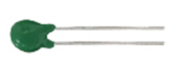
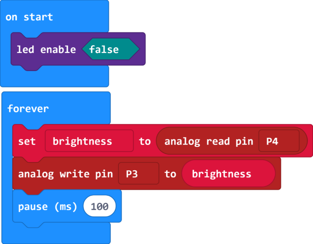
Project 20 Sensitive Light
Description
The photoresistor can change the resistance due to the light intensity.
In this experiment, we can control the LED brightness via a photoresistor.
Parts Required
Micro:bit*1
Micro:bit T-type Expansion Board *1
USB Cable*1
LED*1
220Ω Resistor*1
5MM Photoresistor*1
10KΩ Resistor*1
Breadboard*1
Breadboard Wires
Hooking Up
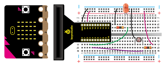
Test Code
Test Result
Upload code and plug in power firstly. The darker the LED will be, the brighter the ambient light sensed by photoresistor is, on the contrary, the LED brightness will be brighter if the ambient light intensity gets darker.
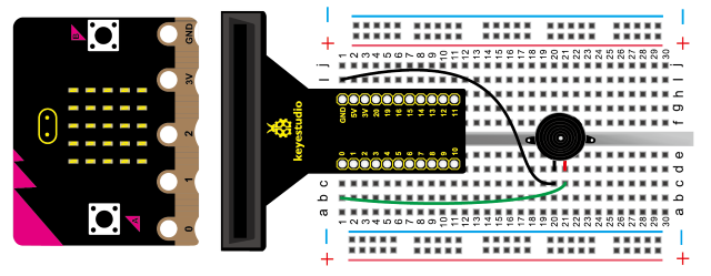
Project 21 Active Buzzer
Description
Active buzzer is widely used as a sound making element on computer, printer, alarm, electronic toy, telephone, timer and more. It has an inner vibration source. Simply connect it with 5V power supply, it can buzz continuously. In the experiment, we input a high level signal to make buzzer emit sound.
Parts Required
Micro:bit *1
Micro:bit T-type Expansion Board *1
USB Cable*1
Active Buzzer*1
Breadboard*1
Breadboard Wires
Hooking Up
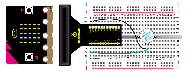
Test Code
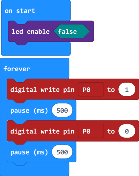
Test Result
Upload code, plug in power firstly. Then buzzer will emit sounds with the interval of 0.5s
Project 22 Passive Buzzer
Description
Normally, the experiment is done with a buzzer.The buzzer we introduced here is a passive buzzer. It cannot be actuated by itself, but by external pulse frequencies. Different frequency produces different sound.
Parts Required
Micro:bit*1
Micro:bit T-type Expansion Board *1
USB Cable*1
Passive Buzzer*1
Breadboard*1
Breadboard Wires
Hooking Up
Test Code
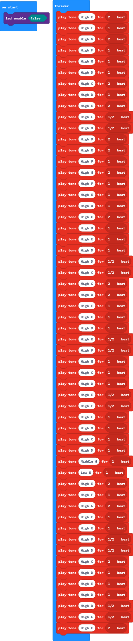
Test Result
Upload code and plug in power firstly. Then we will hear the song“Ode to Joy”
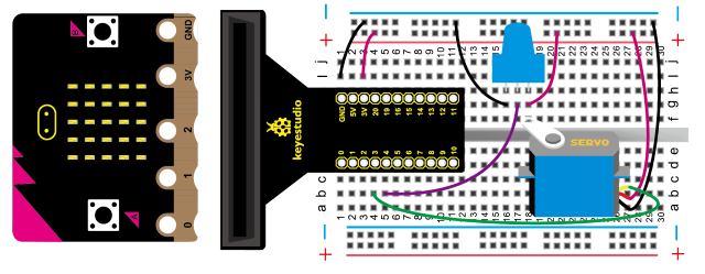
Project 23 Servo Control
1. Description
Servo motor is a position control rotary actuator.
It mainly consists of housing, circuit board, core-less motor, gear and position sensor.
Servo motor comes with many specifications. But all of them have three connection wires, distinguished by brown, red, orange colors (different brand may have different color). Brown one is for GND, red one for power positive, orange one for signal line.
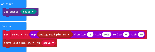
In the experiment, we adjust the rotation angle of a servo via a potentiometer.
Parts Required
Micro:bit*1
Micro:bit T-type Expansion Board *1
USB Cable*1
9G Servo*1
Adjustable Potentiometer*1
Breadboard*1
Breadboard Wires
Note:
The 3-slot AA battery holder is required for power supply due to the large current of driving servo. (battery is not included in the kit)
You only need to interface the Ground port of battery pack to GND of micro:bit
In the test, the micro:bit is supposed to be supplied power with micro USB cable rather than 2-slot AA battery holder.
Hooking Up
Test Code
Test Result
Upload code and plug in power firstly. Then The rotation angle of servo can be controlled by adjustable potentiometer.
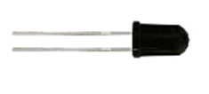
Project 24 Fire Flame
Description
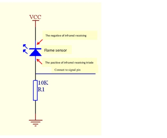
As it fairly sensitive to flame, flame sensor (IR receiving triode) is generally applied to search for fire sources. It utilizes specific infrared receive tube to detect flame, and then converts the brightness into changed level signal.
Therefore, when detecting the fire nearby, it will alarm to remind people to put out the fire in time.
Parts Required
Micro:bit*1
Micro:bit T-type Expansion Board *1
USB Cable*1
Flame Sensor*1
Active Buzzer*1
10KΩ Resistor*1
Breadboard*1
Breadboard Wires
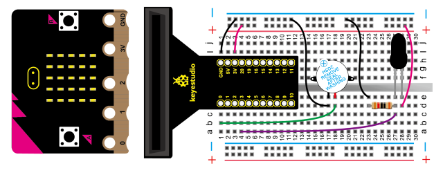
Hooking Up
Sensor connection:
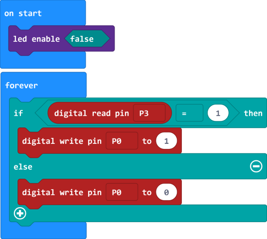
Test Code
Test Result
Upload code and plug in power firstly. The active buzzer will alarm when there is fire nearby the flame sensor; otherwise, it won’t emit sounds.
Project 25: 1-digit LED Segment Display
Description
LED segment display is a semiconductor light-emitting device. Its basic unit is a light-emitting diode (LED).
LED segment display can be divided into 7-segment display and 8-segment display according to the number of segments. 8-segment display has one more LED unit ( for decimal point display) than 7-segment one.
According to the wiring method of LED units, LED segment display can be divided into common anode display and common cathode display. Common anode display refers to the one that combine all the anodes of LED units into one common anode (COM).
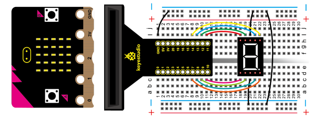
In this experiment, we use a 8-segment display module. A, b, c, d, e, f, g and h are separately connected to p13, p14, p8, p9, p10, p12, p11 and p7.
For the common anode display, connect the common anode (COM) to +5V. When the cathode level of a certain segment is low, the segment is on; when the cathode level of a certain segment is high, the segment is off.
Parts Required
Micro:bit *1
Micro:bit T-type Expansion Board *1
USB Cable*1
1-didit 7-segment Display Module*1
Breadboard*1
Breadboard Wires
Hooking Up
Test Code

Test Result
Upload code and plug in power firstly.
The 1-digit display module shows number from 0 to 9.
Project 26 Ball Tilt Switch
Description
The purpose of tilt switch is to control the on circuit and off.
The switch is connected when it is inclined to one side, however, when inclined to the other side, switch is off.
Parts Required
Micro:bit*1
Micro:bit T-type
Expansion Board *1
USB Cable*1
Ball Tilt Switch*2
LED*2
220Ω 电阻*2
10KΩ Resistor*2
Breadboard*1
Breadboard Wires
Hooking Up
Test Code
Test Result
Wire up, upload code and plug in power firstly. When you tilt the two tilt switches to one side, one LED gets dark and the other gets bright; then one LED is off and the other is on.
Project 27: Read Analog Value
Description
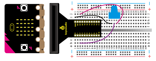
There are plenty of digital ports and analog pins. In fact, micro:bit also has analog ports to read analog value. As shown below:
In this project, we change the analog value of P2 by rotating potentiometer and display value on monitor—-CoolTerm.
Parts Required
Micro:bit*1
Micro:bit T-type Expansion Board *1
USB Cable*1
Adjustable Potentiometer*1
Breadboard*1
Breadboard Wires
Hooking Up
Test Code
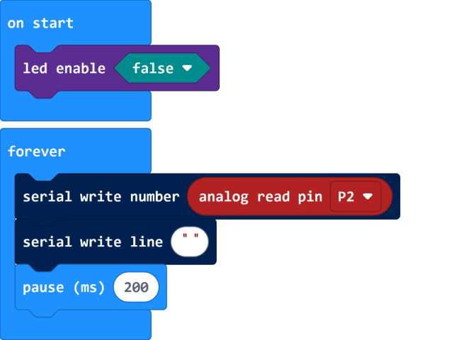
Test Result
Wire up, upload code and plug in power.
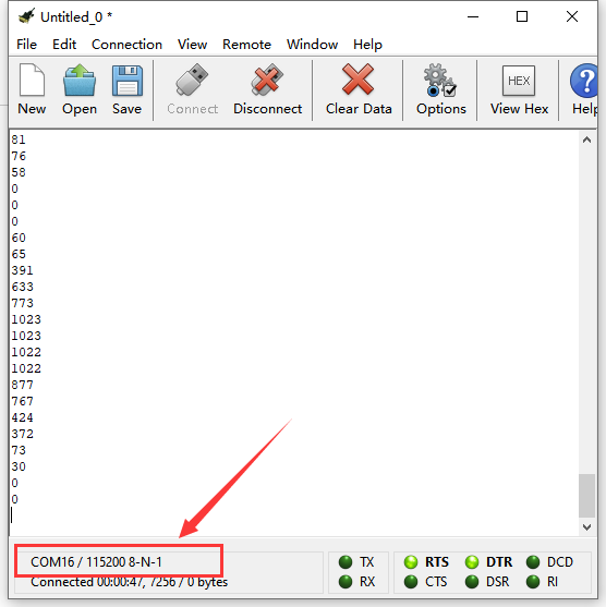
Open“CoolTerm”, click“Options”to select“SerialPort”. Set COM port and 115200 baud rate(the baud rate of USB serial communication of micro:bit V2 is 115200 through the test). And click“OK”and“Connect”.
The monitor shows the value. However, the value varies between 0 and 1023, by the adjustment of potentiometer.
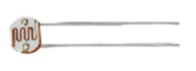
Project 28 : Thermistor Sensor
Description
The thermistor sensor can vary with the change of ambient temperature. In the experiment, after the circuit is built, the temperature change is converted into voltage change. The analog value will be shown on the monitor.
Parts Required
Micro:bit*1
Micro:bit T-type Expansion Board *1
USB Cable*1
5MM Thermistor Sensor*1
10KΩ Resistor*1
Breadboard*1
Breadboard Wires
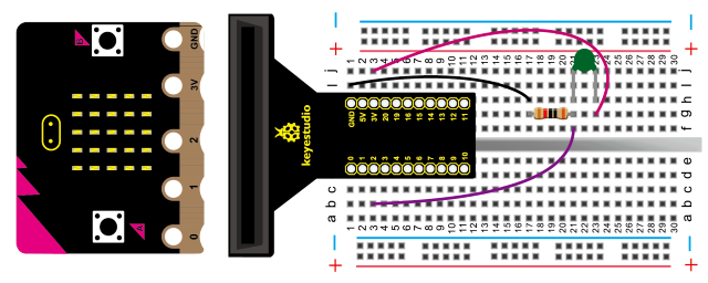
Hooking Up
Test Code
Test Result
Connect the components, upload code and plug in power with USB cable.
Open“CoolTerm”, click“Options”to select“SerialPort”. Set COM port and 115200 baud rate(the baud rate of USB serial communication of micro:bit V2 is 115200 through the test). And click“OK”and“Connect”.
The monitor will show the corresponding value. The analog value will increase when the temperature rises, as shown below;
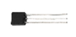
Project 29 LM35 Temperature Sensor
Description
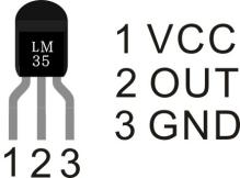
LM35 is a common and easy-to-use temperature sensor. It does not require other hardware. You just need an analog port to make it work. The difficulty lies in compiling the code to convert the analog value it reads into Celsius temperature.
LM35 temperature sensor can produce different voltage by different temperature.
When temperature is 0 ℃, it outputs 0V; if increasing 1 ℃, the output voltage will increase 10 mv. In the experiment, the temperature value will be displayed on monitor.
Note: Don’t reversely connect to LM35 temperature sensor, otherwise, it will be burned out.
Connection Pin
Parts Required
Micro:bit*1
Micro:bit T-type Expansion Board *1
USB Cable*1
LM35DZ*1
Breadboard*1
Breadboard Wires
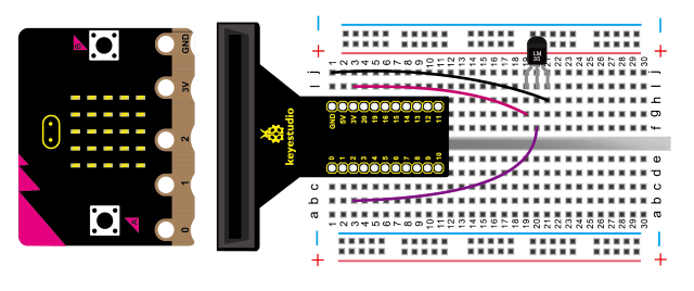
Hooking Up
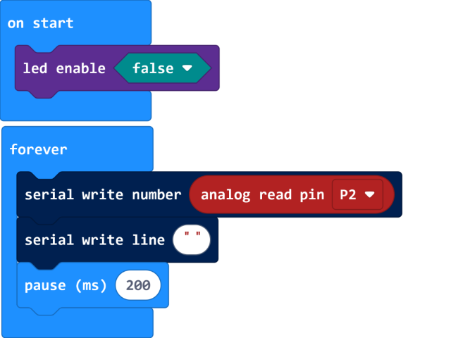
Test Code
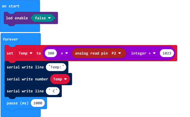
Test Result
Wire up, upload code and plug in power firstly.
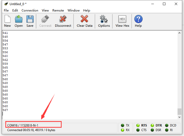
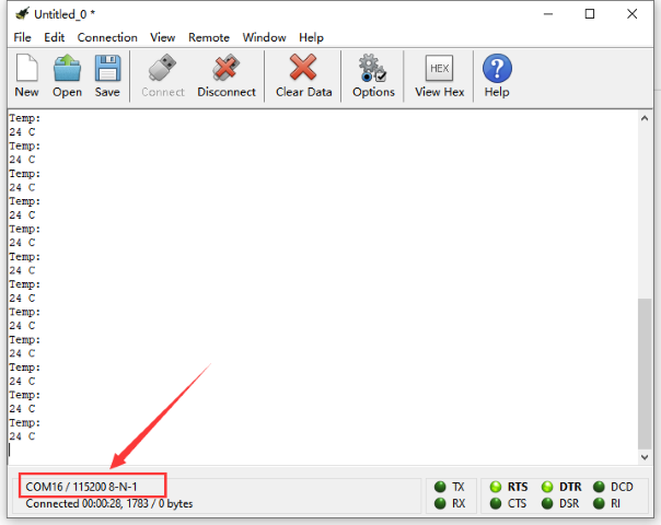
Open“CoolTerm”, click“Options”to select“SerialPort”. Set COM port and 115200 baud rate(the baud rate of USB serial communication of micro:bit V2 is 115200 through the test). And click“OK”and“Connect”.
The serial monitor shows the current ambient temperature value, as shown below:
Resource:
https://fs.keyestudio.com/KS0306
https://makecode.microbit.org/
https://tech.microbit.org/hardware/
https://microbit.org/new-microbit/
https://www.microbit.org/get-started/user-guide/overview/
https://microbit.org/get-started/user-guide/features-in-depth/
https://tech.microbit.org/hardware/edgeconnector/
https://microbit.org/guide/hardware/pins/
https://microbit.org/guide/quick/